A seven-segment display is an electronic array of seven LEDs arranged in a way that can display numerals as well as some alphabetic characters. You can purchase an inexpensive (less than $2) seven-segment display at any electronics-parts stores.
To use a seven-segment display for any practical purpose, you have to connect the display to a digital circuit that’s capable of controlling the individual segments to display meaningful information such as numerals or alphabetic letters. You can do that using a computer to control the individual segments via a parallel-port connection.
A single-digit seven-segment display module is usually wired up as follows: the segments themselves are referred to by the letters a through g. This particular display module is contained in a 14-pin DIP package, but only 8 of the pins are actually used. The anode of each LED segment is connected to one of the pins. The cathodes for all the segments are connected at pin 4.

This is called common-cathode wiring. You can also get 7-segment displays in which the anodes are connected to a common pin; this arrangement is called common-anode wiring.
To control a seven-segment display, you must first connect a positive voltage source to the anode of each of the seven segments. The cathode should be connected to ground. Be sure to use a current-limiting resistor in series with each anode to limit the current that flows through the LEDs.
To drive a seven-segment display from your computer’s parallel port, just connect the anode of each segment through a current-limiting resistor (1 kΩ is typical) to one of the data output pins. The most straightforward way to do that is to connect DATA1 (pin 2) to the a segment, DATA1 (pin 3) to the b segment, and so on until DATA7 is connected to the g segment.
Oct 09, 2018 As in this image shows, its common anode 7-segment display & you have leds are ABCDEFG i.e. You have to give values for each leds. It depend upon segment type when led will glow. Means if its common anode led will glow when given ‘low’ &. The displays common pin is generally used to identify which type of 7-segment display it is. As each LED has two connecting pins, one called the “Anode” and the other called the “Cathode”, there are therefore two types of LED 7-segment display called: Common Cathode (CC) and Common Anode (CA).
After you’ve connected a seven-segment display to the parallel port, you can form numerals or some alphabetic characters by sending the right data to the parallel port.
Thus, to display the numeral 5, use this RELAY command:
To understand why the data values are required, remember that each of the segments in the display is connected to one of the data output pins of the parallel port. Thus, to light a particular combination of segments to form a numeral, you must set the parallel port’s output so that the data pins corresponding to the segments you want lit are HIGH and the remaining pins are LOW.
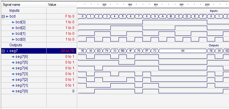
To form the numeral 3, for example, segments a, b, c, d, and g should be turned on. Those segments are connected to data output pins 1, 2, 3, 4, and 7. Thus, you must send a byte of data to the parallel port with the bit positions corresponding to pins 1, 2, 3, 4, and 7 set to the binary value 1 and the other bit positions set to binary 0.
In a binary number, the bit positions are numbered right to left, so the binary pattern you need to send to the parallel port to form the numeral 3 is
The hexadecimal equivalent for this binary number is 4F. Thus, the following command displays the numeral 3:
Listing 4-2 shows a script called COUNTDOWN.BAT that displays a NASA-style countdown from 9 to 0 at 1-second intervals. When the script reaches 0, that numeral flashes repeatedly until you cancel the batch file by pressing Ctrl+C or closing the command window.
Notice in this script that the :LOOP label appears near the end of the listing, not at the beginning. You can place labels anywhere you want in a script. Iio is it love. The GOTOLOOP command at the end of the script causes the script to repeat the last four commands over and over until you interrupt the script by pressing Ctrl+C or closing the command window.